Monday, October 3, 2011

DPHP 17 - It's hot, hard, and dangerous... I need to stay cool

Brownie points for whoever gets that quote.

Probably one of the shorter design focused posts I'll do.  I'm going to be talking about the cooling system.
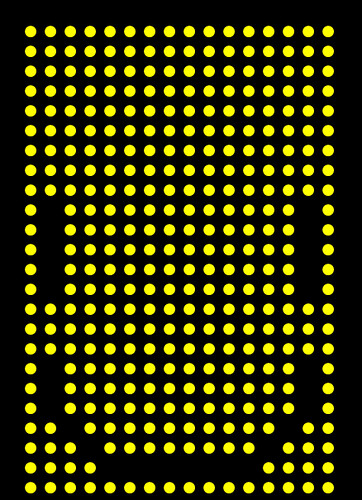
I

RUN

HOT

Fact and case in point.  I've always had a hot metabolism.  I grew up in one of the more 'miserable' climates of Europe and you know what, it suited me just fine.  But the hot, sunny, humid, and even arid places I've been to since then have made me appreciate the power and wonder of central air.  I'm particularly sensitive to the heat.  I'm prone to dehydration, both from my own damn fault (not drinking enough) and my metabolism (I loose a lot of water sweating imperceptibly and perceptibly).  I've had heat exhaustion several times in my life, and probably heat stroke in some of those cases.

So you can imagine, the last thing I want to do is wear an enclosed helmet with maybe 50W of heat generating equipment built into it, while wearing full leathers.  Throw that into the high energy atmosphere and attention of a convention and I probably won't last 15 minutes.  I need something more than just good hydration.  Once again days of google research ensued.

Plenty of options are out there, and I found scenarios for plush encased mascots, to Storm Troopers, to renaissance fair armor.  It all fits into two main categories: evaporative cooling, and phase change cooling.


Evaporative cooling is basically augmenting our bodies normal means of cooling itself: sweating and letting the sweat evaporate.  Despite what lower school science told you those decades ago, water will evaporate at less than 100deg C.  It depends on the air temperature and humidity level, but evaporation below 100deg C does happen.  As that water evaporates, to help it reach that gas state, the water will suck in as much of the surrounding heat energy that it can to help it along.  And that's how it cools you.  If you don't believe me, it's kept you alive up until this point.

Evaporative cooling systems normally work by wearing a fabric that will hold a lot of moisture without feeling particularly 'wet.'  Slowly, that stored water will evaporate to the surroundings and take some heat energy with it, cooling the fabric and you.  However, as anyone who's lived in a swampy area will tell you, it doesn't work very well when humidity is high.  This is because the air is already saturated with water, so there isn't anywhere for evaporating water to go.  So evaporative cooling works great in the desert, but that's about it.


The other system is phase change.  It sounds more complicated than it really is.  Phase change, when talking about personal cooling, really amounts to ice melting.  As ice changes from solid cubes/blocks/chips to water, that process absorbs heat energy.  But another aspect of phase change cooling is that, typically, you start with ice below the freezing point.  So first, your ice warms up to the transition temperature, in this case 0deg C.  Then it starts melting, absorbing more energy.  But now, you still have 0deg C water.  That cold water actually takes more energy to heat 1deg C than the ice does.  Because of these three stages of heating, ice water can in fact absorb a lot of energy.

The commercially available phase change cooling clothing normally amounts to nothing more complicated than ice packs sewn into clothing.  Some have replaceable ice packs, so you can wear one set, use it up, and change it out for another set.  The problem is in fact these packs.  Depending on the outside temperature, your level of activity, and so on, those packs will 'run out' and need to be replaced more often.  You could end up needing a lot of ice packs for any reasonable (or unreasonable) length of costume wearing.  And those cost money.  And they ad a good bit of bulk to your person depending on their size.

Neither of these options are particularly ideal for the design and spirit of my project.  But there is a third option.  I'm not sure when in the days, weeks, and months of research this option turned up, but it did and it's what I'm going with.


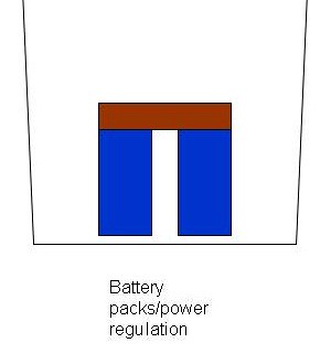
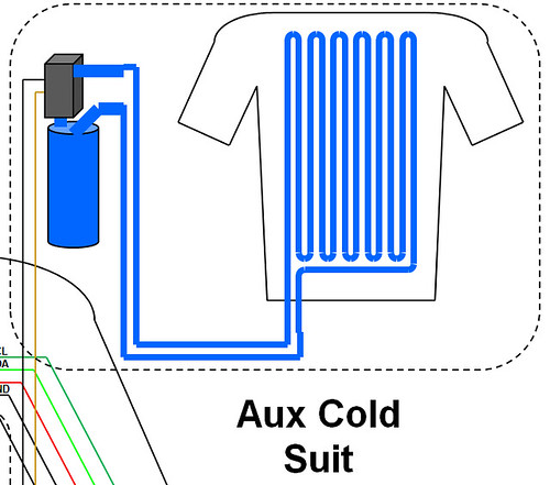
The system I've decided to go with is essentially a portable implementation of the type of cooling systems used for race drivers.  These systems use circulating ice water from a reservoir, pumped around the core of the body via a shirt with small capillary tubing sewn into it.

I like this system for a couple of reasons.  First, it has the level of complexity that I enjoy on this project.  Anything simpler just wouldn't 'fit' as well with what I'm trying to accomplish.  Second, it's fairly low profile, both size wise and the impact it will have with the other systems in the project.  The shirt isn't much thicker than a normal shirt, and the reservoir can pretty much be any size.  Third, it's essentially 'free' to operate for any length of time.  If I use up the current batch of ice water, a trip to the ice machine, or even the bar, will provide the refill I need.  All done without the need to for special ice packs.  Forth, it's expandable and interchangeable, meaning I can use a number of different reservoirs depending on the situation.  Fifth, I can run a 'thermostat' to cycle the pump on and off, improving the comfort and level of cooling depending on my activity, and potentially increasing the duration of a supply of ice water.  As you can tell, I like this solution.

Guess that wasn't as short as I thought it would be...

Friday, July 8, 2011

DPHP 16 - OOP: Object Organizing Pandemonium

For once, I'm going to talk about something current: my move to code base version 3.0.

I decided a while back my code running on the UI controller was a mess and in serious need of an overhaul.  I'm making some minor changes and structure modifications as I do the recode from scratch, but mostly it's about one thing: moving to object oriented programming (OOP).

For those that don't know, OOP is changing the base metaphor of writing computer code.  Normally when you think of code, you think of variables, if statements, for loops, all combined to make functions and eventually whatever code you're trying to write.  It's a pretty straightforward concept and something that plenty of people could probably figure out in a weekend.  OOP is quite different but leveraging the same base tools.

In 'regular' programming you have two type of 'stuff' in your code that's pretty easy to understand: data, and structureData is all variables you calculate, predefine, and so on.  It's hard numbers stored somewhere on the device while it 'does the math.'  Data typically has a specific format depending on the variable you're trying to express.  There are integers for when you only need store and process whole numbers.  There are floats for when you more accuracy and the use of decimal points, but on microcontrollers float processing tends to be rather slow.  There are smaller and bigger versions of these two main types, depending on how big (or accurate in the case of floats) you need your numbers to be.  There are arrays which are just a specific way of defining a big set of variables you want to group together.  Ok, that's fair enough to understand.

Structure is all the stuff you're telling the computer to do with those bits of data.  There's the 'ifs', the 'fors' and also the math you put together to write your code.  The functions you write and the 'main' statement are all structure.  They have a specific format, often known as the 'syntax,' depending on the language you are using (c++, java, etc).  This formatting is critical to the 'compiler' to understand you code; the compiler that makes your code run on your microcontroller or computer.  It's a common, poor mans comparison, but computer code much like the human language can mean different things with minor differences.  For instance "that's a sweet-ass car" means something quite different from "that's a sweet ass-car."  And Yes, that was an XKCD reference.

Ok, I've been babbling on about that stuff for a while, back to the interesting stuff.  So if data is basically just numbers and structure is what you wrap data in to make it do stuff, then what does OOP do differently?  here we introduce objects.  Objects blur the line between where data ends and structure begins.  Objects in code can be like objects in life as well, with numbers and parameters that define and describe them.  Maybe not so clear as life is what else you can put in an object: bits of structure.  Specifically, it's like adding the tools you need to change that object or make it do something.  You're 'baseball' object might have a 'bat' function that makes it fly through the air, for instance.

Where I find Objects useful is in a concept of 'abstraction.'  Most people will tell you a lot of written code is a 'black box' that you put stuff into (inputs) and then it churns for a while and gives you the stuff you want (outputs).  A lot of the time, you don't need to know what happens in the black box, only that it works and it gives you what you want.  That's abstraction: making the stuff you don't really need to know more hidden from you so it doesn't get in your way.

In my UI code, I have tons of what I can 'tracking' variables, variables that are used to keep track of what's running, when it's running, how, etc.  If you want to pass those variables between different functions, those have to be 'global' and visible to all of your functions to work.  But they often have a narrow set of uses to specific bits of code, but they still end up floating around getting in the way of your code when your trying to add other features or debug other problems.  And when you make changes you have to go back and double check that you didn't break a bunch of things you didn't mean to change in the process.

How about a visual example.  On the left is my new code, and on the right is the old code, both starting with setup() at the top:

code comparison

Just looking at them, you wouldn't know that the left example is actually doing a lot more things, with a lot more new features, and doing it a lot more efficiently and directly. Heck, the new code base takes up fewer lines for the setup() and loop() functions than the old setup() had.

It's true, you can generally do the same thing both with and without OOP code.  In fact, I'm hardly using any of the true power of OOP, as you can probably tell from the depth of my description.  But moving to an OOP code base does have generally have an advantage even when you aren't using it's full potential, besides abstraction and tidying things up.  You won't know it until you try it, but OOP tends to suffer less from bugs and problems as you decide to 'upgrade' your code and add new features.  Because you generally have to take the time to lay out you objects and what/where/how they do things, you generally end up with better 'black boxes.'  Other parts of your code don't care about what happens in the box, just the inputs and outputs.  And because that is the case, you can change what's inside the box to your hearts content, because you can only break what's inside the box, not the inputs and outputs that your other code relies on.  Yes, you can make those numbers wrong and irrelevant, but you can't really break the structure of one object with broken structure in another object.  With non-OOP coding, you're probably ending up with big, all encompassing bits of structure that when part of it breaks, all of if breaks.  Eventually you want to stab out your eyes rather than debug something like that.

Long term, the move to OOP has a key advantage in the arduino language: per arduino specs, all libraries are essentially objects, and more commonly/specifically: pre-initialized objects.  I'm not in a rush to release all my code to the public, but I'm pretty sure I will have created some libraries and tools that people will want to have access to for their own projects.  We shall see, but for now I need to make sure that my black boxes work in the first place.

Thursday, June 9, 2011

DPHP 15 - HUD: Headcase Under Duress

In the last post I detailed how I get commands into the system.  Now to discuss how the system gets commands out to me.  Ok, ok, not so much commands but information as status, the other half of the UI pyramid.

Going back two posts, you saw some early images of my UI.  I knew that I was designing the project to be so complex that I needed some form of status monitor so that I didn't have to memorize what the helmet was doing at any one instant.  We are visual creatures.  We can process a lot of information in a very short amount of time by simply looking at something.  So rather than design something with a convoluted series of beeps, whistles, and vibrations like modern smartphones, I needed something visual.

Lets pull up an image from two posts ago:

UI - second notebook picture

Pay attention to the left hand side. You see a couple of sketches. The top is an idea I had to use fiber optics to remotely locate status LEDs. The color and pattern would be used to indicate what's going on. Not exactly pretty or easy to remember.

The second design from the sketchbook is a alphanumeric display/7 segment reflected into the periphery of the eye. This mirror served to give greater flexibility of the placement of LED box, and potentially adjust the perceived size through lensing. A bit better than the fiber optic option, since it could be more recognizable symbols and letters. But still very limited in it's capabilities.

There was also one key problem with both ideas: vision. The lack of vision though the helmet to the outside world. Back in this project's infancy, I assumed I would use a transparent sub-visor and I would see between the LEDs. Well, that went by the wayside pretty quick as the dot pitch of the LEDs got closer and closer together and I realized the shear amount of wiring that would be between my eyes and the outside world.

I got around this problem by using the CMOS camera, combined with some video goggles and of course the on screen display chip. But that now meant I had to design a proper heads up display. And I came up with this:

HUD

So what are you looking at? Well:

1) Display Status Bar.  This shows what is currently running on the display.

2) Randomize Indicator.  This indicators whether or not the display is set to randomly select a new animation after a certain amount of time.

3) Current Power Consumption.  Show in watts.  This is to helpme judge the power draw of the system, and whether I should take actions to reduce power consumption.

4) Remaining Time.  At the current power consumption, how much time is left in the battery.

5) Battery Bar.  Battery icon like you find on almost any battery powered device.

6) Run Time.  The clock showing how long it's been powered up for.  Always useful for keeping track of things.

7) On/Off Indicators.  Indicators symbols for various ancillary devices.  More on these devices in posts to come.

8) Error Messages.  A place for various error messages to occupy.

9) Menu Soft Buttons.  These are soft buttons that correspond to the 8 buttons on each gloves.  I use a fairly straightforward menu tree to organizer everything.

10) Temperature Indicators.  Readings from various sensors on the status of me and my cooling system.

11) Climate Control.  A bunch of settings for the climate control system.

12) Side Bars Status.  What's currently running on the side bars.

All in all, pretty comprehensive.  It's had a few minor evolutionary steps, but mostly has followed this setup since I first laid it out.  This should also give you some indications of sub-systems and components I will detail in the future.

Tuesday, May 24, 2011

DPHP 14 - Star Trek Inspires Everything

It's long been known that Star Trek has inspired a number of technologies over the years.  The cell phone, voice recognition, even the 'hypospray' has a modern day, needless equivalent.  I'd like to start with this image:


And what does this have to do with anything?  The hologram?  Is the helmet a virtual one as well now?  Not really no.  This next picture is another clue:


Getting the idea now?  Yep, this is the idea behind my user interface.  Gloves.  Gloves that are the primary input.  Gloves with buttons built into them.  If you look carefully at the Star Trek image of a game of Strategema, you'll notice the little thimbles that act as the input controllers for the game.  Did Star Trek inspire me to use things mounted to my hands as the input for the Daft Punk Helmet Project?  Probably not, but it was an interesting parallel I stumbled across.

I had the original idea to use gloves as a sort of 'shortcut' buttons that could be used to quickly pull up commonly used animations or images.  Then I discovered the OSD chip that would evolve into my heads up display.  With the ability to have a menu system in place that  I could see and not have to memorize, I could use the shortcut buttons instead as actual input buttons, much like the soft-buttons on cellphones and car stereos.

But how are these gloves going to work?  Well that's were the Peregrine Gaming Glove comes in.  See, regular tactile switches mounted to the side of a glove would be painful to operate, both from the 'poking' factor of the solder joints, and the pain of pressing the switches themselves.  Once I actually tried to press a tactile switch sitting atop my finger nail (my original idea) it was excruciating uncomfortable.  I knew that wasn't going to work.

I tried a few different ideas, including hall effect sensors (magnet sensors) and bend sensors, but wasn't happy with the complexity of the first or 'false positives' the second would introduce (what if I just wanted to pick something up that required closing my hand?).  Finally I came to a rather simple solution: just closing electrical circuits and sensing that input.  Each 'button' would be pressed by the thumb, so replace the button with just a wire acting as an input, and use the thumb to connect the circuit and change the voltage on the 'button' wire.

conductive fabric glove prototype

Originally I was going to do this with conductive thread 'traces' and conductive fabric 'pads' but that was when I discovered the Peregrine gloves.  They use a similar method of electrical connections to generate keyboard pressed for gamers.  The cool part is the components they used.  Instead of conductive thread, they use small diameter stainless steel springs.  Brilliant.

I haven't finalized the design, or even built a completely functional prototype yet.  But the gloves are a winner.  They will be fairly hidden and unobtrusive, adding to the "suspension of disbelief" factor.  They should be pretty easy to use.  They should be error resistant, except grabbing a metal railing in just the wrong way, and my simple tests say that 'way' is a very unnatural and uncomfortable way to grasp something.  They should work a charm.

Monday, May 23, 2011

DPHP 13 - UI Design, aka Ungodly Intricate

So it's been the better part of 2 months since I last wrote a post.  Most probably won't accept that I have been on business trips for all that time, working 12-18 hour days, fighting dragons, etc etc etc.  I don't even really care to be honest, except for the fact that I can finally get back to the interesting stuff on this project.

One of the earliest areas where I could 'stretch my legs' was the design of the user interface, i.e. how the hell I was going to control all this and also know what the hell it was doing.  I still knew nothing about how I was going to do the electronics, but I was sure going to make my life as difficult as I figured I could make it.  Lets try that sentence again, shall we.  I came up with ideas for the user interface based on what I thought I could design and 'make work.'  As I did more research and learned more about more components/code/methods, that design for the user interface evolved and changed.  Lets get stuck in.

Here's something new for everyone, some actual excerpts from my notebook.  Appologies for the shite quality, I used my phone since I'm too lazy to use the scanner.

UI - first notebook picture

Good luck understanding the hieroglyphs I call hand writing.

UI - second notebook picture

This one is a bit more interesting. On the right, You have the layout of an 'arm controller' design that I came up with. Obviously, this was more in keeping with the original costumes, which used arm mounted control panels. Needless to say that has it's difficulties.

On the left is something rather interesting. Probably my first stab at the idea of a 'heads up display.' It's a bit hard to see, harder still to understand, but the idea was to use a handful of RGB LEDs as status indicators. The real interesting idea was to use fiberoptic strands to 1) allow for remotely locating the LEDs based on the space constraints in the helmet, and 2) reduce the brightness somewhat by having the fiber not pointed in the eye but more of a 'peripheral glow.' Also I had the idea of using a 7 segment display or a alphanumeric segment display and a mirror to provide a peripheral indicator. I actually got that idea from the SEGA laser tag guns once upon an age ago.

UI - old overview

UI - animation controller

UI - animation binary

UI - sound controller

Eventually, this concept evolved into what you see above.  The idea was two arm controllers.  One for controlling the display, and one for controlling the playback of sound (since sound was one of my major goals).  I had a handful of ideas on how I could use the buttons on the display controller, one being binary 'combinations' that's very much like dip switch inputs.  The first button would select the group, the second would select the dominant feature, the next would alter that feature, so on and so forth.  Needless to say it was going to involve a lot of memorization of button combinations.  And of course, I had linear potentiometers, because everything is better with sliders.

That was the most comprehensive, and complicated, interface I came up with.  It was like the what the relay did before the transistor was invented (or mass deployed).  You'd be surprised how complicated a circuit you can built with switches and relays.  This was like that.  It was nested menu of button presses and combinations, without giving clear feedback of what was going on.  An old analog aircraft cockpit compared to the modern 'glass cockpit' digital display designs we see today.

This interesting setup got replaced with the design I field currently.  I'll give you a hint, it's infant concept is present in the overall design.  It's just an immature version of it.  We'll cover that in the next installment of DPHP.

Sunday, April 3, 2011

DPHP 12 - Design on a Dime... Apparently that's a TV show

Since I've run out of videos to comment on, and I'm not quite where I want to be with the build before I become 'current' and start discussing that, I've decided the next selection of blog posts will be talking about the design process on the various subsystems of the project.

I design.  A LOT.  I spend hours and days in my notebook, PowerPoint, SolidWorks, whatever the design tool of the hour.  Why?  Because design time is free, at least as far as personal projects are concerned.  It lets me mull over, and over, and over, and over a project.  I suffer from Hyperactive Imagination Disorder (self diagnosed, and no it's not a real affliction).  One of my favorite dialogs with some friends went thusly:

Friend: "Scott, I best describe you as a circle."
Other Friend:  "Why, because he's 'well rounded'?"
Friend:  "No, because goes on an infinite number of tangents."

So why that tangent?  Well, if left to my own devices, ideas spin and spin and spin in my head and I'd never get anything done.  So my design time is more or less just getting all these random tangents down on paper (or sometimes files).  I take all these errant buzzing visions and see if they are practical and meaningful.  This is probably a large contributor to my 'one-upping projects endlessly' problem, I have too many good ideas.  It's going to be expensive now that I know I can actually do the 3D modelling, the electronics, and so on required for said ideas.  But anyways...

So yah, welcome to the musings of my mad head.  Should be fun.

Monday, March 28, 2011

DPHP 11 - Technologic Rehashed


And that's my last video. I readers will be pleased. I should be current from here on out, right?

In this I decided to redo my Conway's Game of Life simulation.  The last one was flawed, it ran for a finite number of cycles and did not have any 'end condition' detection.  So, it was perfectly possible for the screen to hit a repeating or frozen state.  So I fixed that with some interesting use of 'lifetimes' that was linked to the hue of the cell, and some interesting use the neighbor function to detect repeating or frozen screens.

But the bigger 'behind the scenes' change was the use of a new firmware for the rainbowduinos.  Funnily enough, this firmware is very similar to one of the failed firmwares from way back in the infancy of the software development.  My janky original firmware uses multiple send and receive 'sessions' because there is a limit to the size of the send buffer.  As a result, there are largish delays introduced because of the need for the multiple sessions and having to wait after each data transmission.  Well, apparently, when I tried to up that buffer back in the day, I changed only one of the two numbers I was supposed to change to get it work.

Either way, I'm using a new firmware that is far more robust.  It did require a rather large 'going over' of my code, especially the oldest stuff that was coded at a very low level to save on operating memory.  Fun to do?  Not in the slightest.  But everything works so much nicer and faster now.  I haven't done any refresh rate testing yet, but early 'camera testing' doesn't cause any of the usual weirdness like you get when you point at a TV, or like in my very first videos.

So, guess I need to start planning these posts out a bit more, now that I'm out of videos to use as a starting point.  Bugger.

Tuesday, March 22, 2011

DPHP 10 - Making the Robot Rock... Again


Yep. Bad song title pun. Haven't I done enough of those? Not in the slightest. I pride myself on my pseudo-English heritage and mad attention to Top Gear, so I should be able to sprout random one liners til the sun goes down.

Anyways...

So I did sound.  Again.  Why?  Well the first setup, with the Processing sketch and the laptop, would be cumbersome to deploy on the real thing, to put it mildly.  I went so far as to track down the exact model of UMPC (ultra mobile PC) I would have used to run the script and provide the music.  Namely, the Viliv S5.  I was even somewhat willing to pay the ~$500 for the unit.  It'd be a nice toy anyways.  But really, it wasn't really a practical idea.  It meant another device with another battery that would need to be kept charged.  It would mean even more cables.  Not practical.

I learned enough in signals and systems (the class I hated the most in school) to know the theory of what I wanted.  I wanted a discretely calculated (because floating point numbers take a lot of process time on arduinos) FFT (fast Fourier transform).  And I knew that I didn't have the wherewithal to do it myself.

So, I stumbled upon a pre-built FFT library one day on the interwebs, dropped it in, and off we go.  I now have a locally calculated FFT that gives me some pretty lines that dance to the music.  It has some problems.  It probably only registers up to 500Hz and even then it seems to have a ton of noise built into the signal path.  The arduino ADC (analog to digital converter) only reads the positive side of an AC signal from an audio source, so about half the signal is missing.  I did try to get round this with a coupling capacitor and some other circuitry, but the result still isn't perfect.  The typical signal from a MP3 player maxes out around 2.5V, which means your signal is at best 1/2 the voltage you want it to be, and small voltage signals means more noise and more problems.

But I got it done locally on the micro-controllers.  $500 saved.  Job done none the less.

And this brings us to the second half of the video.  Almost more impressive.  Or certainly a more lengthy discussion.  Oh boy.

The side lights.  They're a hug part of most builds, because that's the extent that most others go for with their lights.  Simple reason: you need to see, that gets rid of the front display.  I've gotten around that with the camera and video goggles.  I didn't get around to the side lights until rather late in the game here.

I must one up everything, that's a given.  So, no cellophane covered LEDs here.  Nope, instead I'll continue the RGB trend and give each bar 3 RGB LEDs.  All kinds of coolness ensue as a result.  As you see in the videos, you have scrolling rainbows in the horizontal, in the vertical, and diagonal.  How cool is that?  It basically an extension of the display itself.  Tons of flexibility, limited only to the code I bother to write.

But like everything, there has to be some caveats and some problems.  This is where my new best friend (he who is building another copy of the helmet, otherwise known as ThreeFF) comes in and his innate ability to ask questions.  Plenty of times they're questions and problems I've thought out (like how do you see in the dark: headlights), and I explain as much.  But it's very helpful when he calls out the bits I haven't thought of.

He points out, simply, that if I used a rainbow, like you see in the video, I'm essentially using 1/6 the power of the main display (1 rainbowduino instead of 6) to light up roughly the same surface area with the side bars.  Yah, problems.  This eventually turned into an epic saga, in which I became knowledgeable about almost every off the shelf LED lighting system in the hobby electronics scene, from shiftbrites, BlinkMs, bliptronics, etc.  But as always that's discussion for other another time.

Sunday, March 13, 2011

DPHP 9 - A.I. = Attenuated Intelligence


Yep. Pong. Seriously, why wouldn't you?  The hard part?  Faking being human, and failing like a real human.  I mean, I could do the MONOCRON thing and have it tell time our just count up in increments, but wheres the fun in that?  No, I wanted some AI's that would play against each other, relatively evenly matched.  Apparently it's the sign of a good AI if it can play itself and stay relatively matched.  Bonus points if it manages to use different tactics and still score very close.  But anyways, evenly matched AI's are mostly likely to just volley endlessly, which isn't very sporting, or interesting, or technically challenging, or going to sound impressive in programming circles, etc etc. 

The breakthrough came when I included some 'random tiring' where one of the AI's would reduce in skill over time.  Theoretically, this could lead to an interesting situation where a paddle would 'negatively follow' the ball and move in the opposite direction, but hasn't happened yet.  I will worship the day that it does though, especially if both paddles manage to go negative at the same time.

Also, Pacman sprites fit on my display.  Neat.  I wish more of the Megaman sprites fit.

Wednesday, February 23, 2011

DPHP 8 - The Most Signiture 5 Notes Ever

And no, it's not Jaws, that's only 2 notes. We can't all be John Williams.

But first, a house keeping video.


Right, so, that's out of the way.  This is a lot of 'house keeping' animations, ones that I had sitting in notebooks and as little notes on my design docs.  I had a 'lull' in code work so they came to life.  If you're so inclined, have a read of the description.

Now, onto the good stuff.  I have a few static images in there (if you look carefully you'll see my Alma mater).  Around 0.38 it gets interesting.


This was a continuation of my 'must include sound' goal, as well as being one of the earliest ideas I came up with for animations, behind the pinwheel, rain, and the spectrum analyzer.  Who doesn't know the 5 note progression from Close Encounters of the Third Kind?  I remember knowing that note progression even before I had seen the film.  In this video it's accomplished with a rather meek buzzer, so it sounds rather grungy.

The animation came about as a sort of 'happenstance.'  I updated the arduino IDE and noticed that a new function had been added to the base library: tone().  Turns out you could tone generate on any of the pins.  Spiffy.  A bit of research into note frequencies and several hours of staring at the film footage and I had a timing and color correct reproduction of the movie scene.  Well, as best I could generate that is.  It's hard to tell in the video, but yes, the colors are the same as the ones used on the big 'light board' in the background of the film.  The placement is different, but that was a style decision on my part.

the fireworks you've seen before, but this is a 'fixed' version.  Brownie points to the person who figures out what was wrong in the original and was fixed in this version.

Finally in the video, another one of my infinitely useful tool functions.  Text.  It took a painfully long time and painfully levels of creative energy to make ASCII characters that are only 4 pixels wide by 6 pixels tall.  You have no idea how hard it is to replicate the alphabet with only 24 dots.  But that pain was singular and it made if much easier to have text marques.  And with text marquees is much easier to present technical information to a viewer.  While all the other static images, emotions, etc, it should be easy to carry on a coversation (at least a basic one).  But when asked specific, direct questions, it's best to rely on ordinary text.  Imagine giving signals of some sort to indicated any of the stuff presented in the text.  Yikes.

Monday, February 21, 2011

DPHP 7 - Reinventing the Wheel... Well, Really, the Line


While I did lie before, this time it's true, I had actually moved to the Arduino Mega at this point.  And then things got really complicated.

This was a the age when I was fighting an uphill battle with my experience and the lack of 'assistance' and 'direction' I was getting from others.  For instance, that first animation, took maybe an hour to code and debug.  After probably 6 hours of failing to write my own line drawing routine.

The problem was, I had never heard of Breshenham's line algorythm.  Why should I have, I'm an aerospace major and had only taken basic coding and numerical methods.  I hadn't taken a graphics class, heck, I hadn't even taken a autonomous systems class (though I was interested but my course load and schedule never allowed it).  I never had need to draw a line from A to B.  The truely sad part was how hard it was for me to finally combine the right search terms to get a hint at Breshenham.  It wasn't pretty.

After finally being able to draw a line from one point to another, I could accomplish much of the above animations.  The bouncing line is pretty simple, track a few points and connect them with points.  The pinwheel is just some lines from the center and some fading code thrown in.  So this must be what it's like when you code with reuse and functionality in mind.  It's wonderful.

I was starting to realize that with enough processing space and code space, you could accomplish a lot more.  Processing power/time isn't so much a problem more often than not, since you can often trade memory usage for speed.  And it is amazing what you can accomplish even when your processor does one thing and only one thing at a time.  And it's most amazing what you can cobble together when you have no idea what you're doing.

Thursday, February 17, 2011

DPHP 6 - Fighter Plane in a Helmet

It's amazing how quickly the one a day promise falls by the wayside. Excuses excuse, etc etc, blah blah blah. The honest fact is it's a work week from hell, where the world is expected and as much as possible needs to be delivered. So I'm behind a few days. Here's getting back on the bus.


You may be noticing a trend here.  For the longest time, my youtube videos have been the best kept records of this project.  I often put far too technical an explanation into the description, but at least it's somewhere.

I've made mention of what you're seeing about before.  I once again, there's a nice narative to explain what's going on.

Simply put, there is no way to see through the LED display matrix.  Even if the sub visor were made transparent, the backglow of the LEDs would be bright enough and close enough to the face to completely wash out any other light source, let alone causing potential damage from the proximity and brightness.  So how does one fix this?  Well, the obvious choice is with a camera and video goggles.  The camera can be mounted elsewhere in the helmet with an adequate view point, and the goggles go infront of the eyes, where they do the most good.

But clearly, that is too simple a solution, far to simple for the scope and scale of this project.  After some research, I came up an On Screen Display (OSD) prototyping chip on sparkfun, based on a MAX7456.  This way I could overlay text onto a standard NTSC video signal, i.e. what coming out of the camera and going into the video goggles.  Bingo.

And another one of my main engineering hurdles rears it's head.  Animations, for the most part, require almost all of the processing time of the microcontroller.  Maybe not the ones you've seen in the first and second round animations, but some of my later ones certainly require every single cycle in order to have a reasonable refresh rate.  Where am I going to find the processing time/cycles to run all the background stuff to drive an OSD chip?  The answer is a second controller, known as the UI controller, in addition to the one used to run the animations, now known as the SHOW controller.


Ok, so now I have a whole second microcontroller to play with, and it's job is only to interface with the user, tell the SHOW what to do.  Here's a breakdown of the features:

Power
-Report the voltage of the primary and secondary power batteries
-Report the amp draw from the primary battery
-Integrate voltage and amp draw to calculate used power, and remaining power in the battery

Climate Control
-Report the temperatures measured by a couple of sensors
-Turn on and off cooling devices based on temperature data
-Provide automation of the climate control functions

Status Display (OSD)
-Report what is currently running on the display
-Report the current menu interface state
-Report climate control and power status information

Command Control
-Accept inputs from the user
-Track state information to/from the user and to/from the SHOW microcontroller
-Send appropriate commands to the SHOW microcontroller

So how is all this accomplished?  Well, I have the following bits and bobs connected to the UI micro:

component - purpose - protocol

>MAX7456 - on screen display - SPI
>ACS712 - current sensor - ADC
>DS18B20 - temperature sensor - 1Wire
>Voltage divider - Voltage sensor - ADC
>Glove buttons - user input - I2C
>PNP MOSFET - power switching to cooling components - DIO

We'll save how all this breaks down for another day.  There are a lot of systems and subsystems to explain, that's for sure.

Sunday, February 13, 2011

DPHP 5 - Code Occupies the Space of it's Container


Yep, as the video title suggests, this was my second collection of animations.  Why is this one special?  Well, at this point I had moved off of the bog standard Arduino Diecimila with it's ATega168 processor to an Arduino Mega with a ATmega1280.  Why?  Well, the 168 has 1kB of SRAM, or 'operating memory' similar to the RAM in your computer or laptop.  The difference is when you run out of operating memory on a microcontroller, you don't have a page file to save your bacon.  Instead, it all goes to pot and it's nearly impossible to tell why or how.  And why is 1kB not enough space?  Well, let's look at the display.  I'm sure people hate math but bear with me.

One pixel of the display needs 12bits of information to describe it, in other words 4 bits per color.  That means that the whole display, which is 24x16 pixels, is 4608 bits, or divide you divide by 8, 576 bytes of information.  So, just to store a 'full copy' of all the information needed to send ONE frame to the display, you would be using over half of the available memory.  Specifically, 576/1024 =  56.25% of your available memory.  Yikes.

This made things like 'hue based colors' impossible with only 1kB of memory.  In the hue based color system I use, a single number correlates to a part of the color spectrum I can reproduce on my system (4096 total colors) at a fixed brightness.  Therefore, I fix the 'saturation' and 'brightness' values used in standard HSB/HSL color schemes.  One of these color values, for one pixel, requires a byte to store.  So that's 384 bytes to store the full display.  But, in order to send those colors to the display, you would need to convert from the hue buffer to the 12bit RGB buffer, which is 576 bytes.  So your total memory footprint before you even write code (which chews up memory with loops, if statements, etc) is going to be 960 bytes.  So you have 64 bytes left for everything else.  and I mean everything else.  There's just no way that can be done.

So obviously, I moved to a larger and more powerful controller ASAP.

Ok, Ok, I lied, I wasn't using the Arduino Mega just yet when that video was made, but I was finding out very quickly that the scale and scope of my project would require, nay necessitate the use of a controller with more memory.  In fact, probably a lot more.  Hence the use of the Mega with it's 8kB of memory.  I haven't run into a (memory related) problem since.

Saturday, February 12, 2011

DPHP 4 - Rewriting History... In Code

Suffice it to say, I won't make this one very long.  Not everyone can read about coding approaches and enjoy it.  I guess I can liven things up a bit with some of my youtube work.

With rainbowduinos in hand, I began to code.  I had to open up the capabilities of the rainbow to allow for more direct control from a master arduino.  Specifically, the rainbows came with no way to send 'pixel by pixel' information, only text characters and a few other simplistic functions.  I changed that pretty quickly.  Well, quickly in relative terms to the total ungodly amount of time I've spent on this.


From there I included what I like to call chromatics.  These were abbreviated data structures that would use a simple on/off state for each pixel, and then apply a color to all of the pixels.  With that I made monochromatic, dichromatic, and trichromatic data types for one, two, and three colors respectively.  This reduced the bottle necking of my kludged together rainbowduino code.  I've since abandoned that code set, but I keep the data types living on in a fair number of my animations.


From there I made my first animations.  Not rocket science all of them, I admit, but it warmed me of to the methods and concepts of matrix and display manipulation that would become the bread and butter of most of my code.


And finally, I made my one of my first masterpieces.  One of the original 'when pigs fly' ideas I had at the very beginning of the project in 2006.  Ideas I had had but over the following years had taken on a sort of mythical status, something that would disappear into the pages of history unrecorded.  But, after days of trial and error, reteaching myself the fundamentals of programming, and one of the most convoluted and painful debugging sessions in my life, I had accomplished the impossible.  I had made a spectrum analyzer, one that responded to sound.  I had fulfilled one of my original requirements for the project.

Enjoy.


Thursday, February 10, 2011

DPHP 3 - Electronics Genesis

Onto the start of the heart and soul of the project.  I'm sure for most the helmet itself would seem like the fulcrum upon which the rest of the project pivots, and you're probably right.  But if you want to talk about where most of the development hours, effort, learning, blood, sweat, and tears (honestly) went in this project, it would be into the electronics.

From the get go I knew this was going to be the biggest part of the project, which more than anything else the functionality of the LEDs and all that would make or break the project.  It was where things would shine, where things that had never existed would be created, where I could be a true innovator.  And also the area where I knew almost nothing.

I often tell the story of how I became an aerospace engineer when I explain what it was like getting into the electronics of this project.

Today will be no exception.

Freshman year at university, like many others, I knew roughly what I wanted to study.  Luckily, all freshman are taking general required classes their first year anyways, so they get the year to also take some intro classes.  I had built many a gaming desktop in my teens and loved the power and flexibility inherent in a computing platform, so naturally I thought computer science would be the major for me.  My intro to programming class taught me otherwise.

We programmed in a rather arcane language that was LISP based, which to this day I have no idea what that implies other than it's not C based (like C, C++, java, and oodles more).  For one nights homework I spent three hours debugging my code until I realized I had misspelled LAMBDA.  That's how hard it was to code in this language.  That's how bad the editor was at pointing out compile time errors (which to this day I don't think it could throw compile time errors, it was all or nothing).  That's how annoying it was for me, the king of spelling mistakes.  And that's how I didn't become a Comp Sci major.

Conversely, my intro to aerospace class was completely different.  We built all kinds of things, from paper clip parachutes to radio controlled helium balloon racers.  We did math that (although simplified) was the same math you used to get something into space.  We looked at the fundamentals of how the whole commercial air travel business was one giant, well balanced, and sometimes broken equation.  It was interesting, and that's why I became an aerospace major.

Despite going into aerospace, I still had to learn to code.  You can't be an engineer today (or even a mathematician or scientist) without at least being able to write an integrator in excel, or use data analysis functions in MATLAB.  But on the first programming homework assignment, which was in the Ada95 language, I knew I had picked the right major.  I had a number of spelling and syntax mistakes, and for each one the compiler caught it.  For each one it even would pop up a little text string at the bottom asking "I noticed you put a ':' here when you probably meant to put a ';' , would you like me to change it?".  Ok, it may not have been exactly like that, but to a person who is plagued with spelling and syntax problems, it was a godsend.  I had picked the right major.

So hopefully now you understand what it was like in the early days of this project.  What comes next (or more likely many installments from now) may astound you, but keep in mind it comes from the same mind that coded three different line drawing functions of his own before stumbling onto Breshenham's line algorythm.  It hasn't been easy.

So when did electronic genesis happen?  Some time in June or July of 2009.  When I discovered the Rainbowduino from Seeed Studio.  No, that's not a typo.


In the year preceding I had learned about row & column multiplexing, current sinks and sources, persistence of vision, and all  that good stuff.  But I barely new anything beyond basic V=IR circuit, and even less about microcontrollers.  I had built an RFID door unlocker with a servo to pull the door handle, but that was largely from borrowed code and ideas from other peoples projects.  And looking back the code was so hideous it makes me cringe.  There was no way I was going to be able to build my own circuit to drive all of those LEDs.  I had to have an off the shelf solution, at least to get me started otherwise it would have been far too overwhelming.


I knew of Sparkfun and their SPI based LED matrices.  But they weren't ideal.  SPI sounded really scary, what with the very loose standards surrounding it, and Spark's example code was even more off putting.  Plus, the pin-out of the backpack board was designed for a specific matrix, and that pin-out was all over the place with no apparent rhyme or reason.  It would have been incredibly painful to hard wire the helmet display given the lack of order.

Then I found the rainbowduino.
It was RGB, so lots of colors.  Joy.
It was based on a ATMega168, and the code was in the arduino language.  Joy joy.
It was cheap, way cheaper than Sparkfun's offering.  Joy of all joys.

So I put in an order for 6 of them and 6 prefabbed matrices for prototyping purposes.

Wednesday, February 9, 2011

DPHP 2 - Design Docs & The Age of PowerPoint

During all of the CAD work that took place, I began to flesh out the specifications that would make up the rest of the project.  Here they are in no particular order, although accompanies by nice little blurbs about how they came to be.

A resolution of 16 wide by 24 tall

1 resolution

I was loony enough to count the LEDs on the original Guy-Man helmet at one point.  I think it was something like 15 wide by 33 tall.  That seemed a really arbitrary number, so I settled on 16x24.  It was a multiple of 8, the number of bits in a byte, often a good thing when working with microcontrollers and computers.  it's magically become the ideal size/resolution for innumerable reasons since then.

RGB color scheme

2 RGB

In one of the many aspects of this project that "one ups" the original, I chose to have an RGB (red green blue) color scheme rather than the RGY (red green, combined yellow) of the original helmet.  It seems like in decade or so since Daft Punk's robot debut, things should advance a bit.  Whats one more color right?  With RGB, I can replicate (most of) the rainbow.

Heads up display

3 OSD

This came largely out of necessity at first, but of course needed to be one upped on it's own.  At first it was a small CMOS camera combined with a pair of video goggles, like the kind you find in the back of the Sky Mall magazine.  But if one has a camera and video goggles, one should naturally include an onscreen overlay status display, right?

Suspension of disbelief

4 suspension

This was largely an approach, more than a feature.  Call it the Turing test of a robot costume.  I wanted to have a conversation (albeit limited) with someone without it them pausing to think what's going on.  I didn't want to be the man in the suit or the man pulling the strings.  I didn't want there to be a man at all, at least in peoples eyes.  You'll see this idea at the heart of a lot of the work on this project as we go along.

Local control

5 local control

largely connected to the above point, I want to be in control, inside the outfit.  It's not a narcissism (not too much anyway) but again to remove the puppet and strings problem.  It's no fun to be pulling the strings, and it's no fun to be pulled either.

Portable power

6 batteries

What fun is all this is it can't run on batteries?  Who want's to hop from power outlet to power outlet at a convention?  Who wants to explain that the getup is a lot cooler if it's plugged in?  All I can say is thank the powers that be for lipo batteries.

Personal cooling

7 cold suit

Fans.  the helmet is going to need a number of fans.  You know, race car drivers have those water cooled undergarments as well...

Sound input

8 music

Daft Punk are all about the music, why shouldn't a replica be as well.  Stay tuned.

As practical as possible

9 practical

Clearly the helmet is going to have some heft.  Clearly, there are going to be a lot of wires and a lot of connectors.  Clearly I will have limited mobility and vision.  Clearly I will need a bouncer/handler to keep an eye on me and an eye out for me.  But how clearly will I be able to see in low light conditions?  There's a fix for that too.

I have powerpoint upon powerpoint of ideas I've had, wiring diagrams, cheat sheets, and even more in sketch books.We'll call this the starting point for the cliff notes.

Tuesday, February 8, 2011

DPHP 1 - The Beginnings

I've decided that I'm going to part and parcel up the posts related to the Daft Punk Helmet Project, at least until the point where I'm up to date with current events.  So allow me to start with the project at it's earliest inception.

The start date for the maelstrom of ideas that would evolve and become DPHP was mid October, 2006.  I was talking with an old friend from high school about Daft Punk, a musical duo I had 'gotten back into' after discovering the full Interstella 5555 movie (and not just the handful of music videos) and the fairly recent release of their Human After All album.  I had managed to get my friend interested enough to watch Interstella 5555 (house/electronica really wasn't his scene so the music was lost on him).  After having scene the film, the conversation when something like this:

Friend: Dude! you should totally go as one of the guy from that movie for Halloween!
Me: You'll need to be more specific, there were bunches of people in the movie, all of them cartoons technically.
Friend: The robot guys you were talking about! Daft Junk or whatever.  You should totally put all those lights in it and stuff!  That would be sweet!
Me: Um, A) Halloween is like 10 days way, B) that requires a bunch of tools I don' have access to, and C) I'm aerospace, not electrical engineering.  I'd have no idea where to start with the electronics.
Friend: But you go to [leading engineering university].

Those last four words would be my undoing, so to speak.  With that I took up the mantle, the challenge of building a replica Guy-Manuel de Homem-Christo.  But it wasn't to be just any replica.  I had to improve upon every aspect of the original design.  You'll slowly find out about all that as we go along.

So with the gauntlet thrown down, I decided to begin with generating a solid CAD model of the helmet.  I knew that I wouldn't be making the helmet any time soon, but I liked the project simply as a technical exercise.  I'd spent the previous summer CAD'ing up my own version of the Vic Viper ship from the Gradius series of games.  I learned a lot in that process, and figured the Guy-Man helmet would be a nice new project.

So, who wants pretty pictures?  Thought so.

1 round 1 color

This is the very first model I ever made of the helmet, Round 1, in stunning technicolor.  Eh, maybe not the last bit.  Looking back it was an extremely rough model based on some even worse references.  I used two screen grabs from the 'Grammys' sequence of Interstella 5555.  Needless to say they had all kinda of issues, including simulated lens distortion.  It gets better trust me.

2 round 1 control panel

Along with that design I had the 'rather outdated' control system in the form of arm mounted control panels.  Needless to say not the easiest things to operate in armored gloves and a helmet full of lights.  Still, not bad looking if I do say so myself.

3 reamped

4 reamped front

The second generation of the helmet, known as Amped.  I had learned a lot from the first one, and started replacing a massive number of the features that made up the helmet.  I sloped in the sides for a more organic look.  The chin angled down more and it's bottom curled under, again, making it more organic and lifelike.  This is where it started to look like something 'Human After All.'

5 reamplified assembly

When stuff started getting really complicated, aka Amplified.  Largely based off of the previous Amped generation, though again with some of the features improved in an almost indistinguishable way.  What I really spent my effort on was making it practical and manufacture-able.  I included the 'sub-visor' which would hold all of the main display LEDs, the side bars, auxiliary LEDs, so on and so forth.  If you look really carefully, you'll even see the 'swing arms' from a dead design decision.  In the interest of ventilation and ease of wear-ability, I thought it would be a nice feature to have the visor hinge open.  Needless to say it was a complicated concept and died very quickly along the way.

6 equalized assembly

And this is very close to what we're working with right now, almost.  This is far more attractive design, isn't it?  Angular, sweeping, contoured, organic, and whatever industrial design buzz words you want to use.  Needless to say it's damn close to the real thing, but with my own twist and opinion on the design.  I guess this is as good a place to stop as any.  We'll get to all the colored bits you see in due time, I promise.

Monday, February 7, 2011

Hi, I'm Scott, and I live on a 3 Name Basis

Yep, you read that right.  I live on a three name basis.  Why?  Well, I have the (mis)fortune of having three boys' first names as my first, middle, and last name.  I've gone by the first and last name interchangeably most of my life, but sadly people have also called me by the middle name expecting a response.  This has been out of necessity.  Every teacher I ever had would see the last name on the attendance sheet and instinctively call me by that name.  It's become a pet peeve, like people touching my hair, but that's a story for a different day.

Why do I feel the need for a blog?  Well, largely, as a central place to deposit all of the work I've been doing on my Daft Punk Helmet Project, an attempt to recreate a Guy-Manuel helmet with all the trimmings, except that the design has been turned up to eleven more times than I can count.  Suffice it to say, the design has inclusions for everything.

I won't pigeon hole my posts to just that project, however.  Maybe I'll touch on life lessons, maybe I'll touch on productivity tweaks, maybe I'll rant a bit.  You'll just have to see.  Let's hope it's not boring.